DP Based Flowmeter
- Home
- DP Based Flowmeter
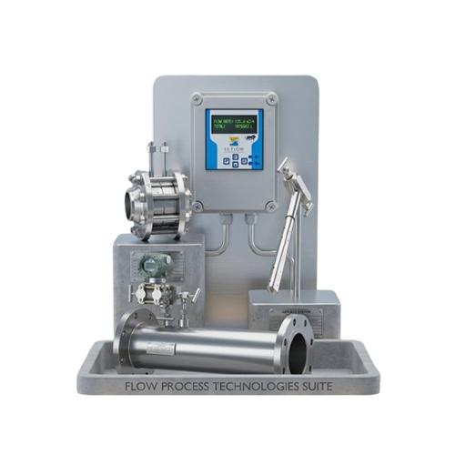
DP Based Flowmeter
| FEATURE | DESCRIPTION |
|---|---|
| Simple Construction | No moving parts |
| Low Cost | Economical solution |
| Wide Application | Works with liquid, gas & steam |
| High Reliability | Rugged and durable |
| Easy Maintenance | Minimal servicing required |
| High Pressure & Temperature | Suitable for demanding industrial conditions |
| Standardized Technology | Based on proven principle |
| Large Pipe Compatibility | Good for large pipe sizes |
Key Features
Proven & Reliable Technology
• Based on Bernoulli’s Principle
• Widely used and industry-accepted method for flow measurement
• Widely used and industry-accepted method for flow measurement
Wide Application Range
• Suitable for liquids, gases, and steam
• Works efficiently in harsh industrial environments
• Works efficiently in harsh industrial environments
Simple & Robust Construction
• No moving parts (in primary elements like orifice plate)
• Long service life with minimal wear
• Long service life with minimal wear
Cost-Effective Solution
• Lower initial cost compared to advanced flow meters
• Economical for large pipe sizes
• Economical for large pipe sizes
Variety of Primary Elements
• Compatible with:
– Orifice Plate
– Venturi Tube
– Flow Nozzle
– Pitot Tube
• Flexible for different applications
– Orifice Plate
– Venturi Tube
– Flow Nozzle
– Pitot Tube
• Flexible for different applications
High Temperature & Pressure Capability
• Suitable for extreme operating conditions
• Ideal for steam and high-pressure gas systems
• Ideal for steam and high-pressure gas systems
Standardized Design
• Designed as per international standards:
– ISO 5167
– ASME guidelines
– ISO 5167
– ASME guidelines
Good Accuracy
• Typical accuracy: ±1% to ±2%
• Can be improved with proper calibration
• Can be improved with proper calibration
Easy Integration
• Works with DP Transmitters
• Output signals:
– 4–20 mA
– HART / Digital communication
• Easily connects with PLC / SCADA systems
• Output signals:
– 4–20 mA
– HART / Digital communication
• Easily connects with PLC / SCADA systems
Suitable for Large Pipe Sizes
• No limitation on pipe diameter
• Commonly used in large pipelines
• Commonly used in large pipelines
Low Maintenance
• Minimal maintenance due to no moving parts
• Periodic inspection required for primary elements
• Periodic inspection required for primary elements
Working Principle
A Differential Pressure Flow Meter works on the principle of Bernoulli’s Principle, which states that an increase in fluid velocity results in a decrease in pressure.
Basic Operation
- A primary element (such as an orifice plate, venturi, or flow nozzle) is installed in the pipeline.
- When fluid flows through this restriction:
o The velocity increases
o The pressure decreases - This creates a pressure difference (ΔP) between upstream and downstream sides.
Pressure Measurement - Two pressure tapping points are provided:
o Upstream (High Pressure)
o Downstream (Low Pressure) - The difference between these pressures is measured using a DP transmitter.
Flow Calculation - The flow rate is proportional to the square root of the differential pressure:
Where:
o Q = Flow rate
o ΔP = Differential pressure
Industrial Applications
Differential Pressure (DP) Flow Meter – Industrial Applications
Oil & Gas Industry
• Measurement of crude oil, natural gas, and refined fuels
• Used in pipeline flow monitoring
• Ideal for custody transfer (with proper calibration)
• Used in pipeline flow monitoring
• Ideal for custody transfer (with proper calibration)
Power Plants
• Measurement of steam flow in boilers and turbines
• Monitoring of feed water and cooling water
• Used in energy management systems
• Monitoring of feed water and cooling water
• Used in energy management systems
Chemical & Petrochemical Industry
• Flow measurement of chemicals, acids, and solvents
• Suitable for high temperature and pressure processes
• Used in reactors and process lines
• Suitable for high temperature and pressure processes
• Used in reactors and process lines
Refinery Applications
• Measurement of fuel gas, flare gas, and process fluids
• Used in distillation and cracking units
• Used in distillation and cracking units
Water & Wastewater Industry
• Measurement of raw water, treated water, and effluent
• Used in water treatment plants and distribution systems
• Used in water treatment plants and distribution systems
Food & Beverage Industry
• Measurement of clean liquids (milk, juice, edible oil)
• Used in batching and process control systems
• Used in batching and process control systems
Pharmaceutical Industry
• Flow measurement in clean and sterile processes
• Used for precise dosing and formulation
• Used for precise dosing and formulation
Steam & Gas Distribution Systems
• Measurement of compressed air, steam, and industrial gases
• Widely used in utility lines
• Widely used in utility lines
HVAC & Building Services
• Monitoring of air flow and chilled water systems
• Used in energy optimization
• Used in energy optimization
General Industrial Process Control
• Integrated with PLC / SCADA systems
• Used for real-time monitoring and automation
• Used for real-time monitoring and automation
Technical Specifications
1. GENERAL SPECIFICATIONS
| Parameter | Specification |
|---|---|
| Measurement Principle | Bernoulli’s Principle (Differential Pressure) |
| Measured Fluid | Liquid, Gas, Steam |
| Flow Range | Depends on primary element & pipe size |
| Accuracy | ±1% to ±2% of Full Scale |
| Repeatability | ±0.1% to ±0.3% |
| Output Signal | 4–20 mA, HART / Digital |
| Display | LCD / Digital (Optional) |
2. PRIMARY ELEMENT DETAILS
| Parameter | Specification |
|---|---|
| Primary Elements | Orifice Plate, Venturi Tube, & Pitot Tube |
| Line Size | DN15 to DN2000 |
| Beta Ratio (β) | 0.2 to 0.75 |
| Mounting Type | Flange / Wafer / In-line |
3. OPERATING CONDITIONS
| Parameter | Specification |
|---|---|
| Operating Pressure | Up to 400 bar |
| Operating Temperature | -50°C to +400°C |
| Ambient Temperature | -20°C to +60°C |
| Fluid Condition | Clean / Dirty (depends on element) |
4. MATERIAL OF CONSTRUCTION
| Component | Material |
|---|---|
| Primary Element | SS304 / SS316 / Carbon Steel |
| Body / Fittings | Stainless Steel / Alloy Steel |
| Gaskets | PTFE / Graphite |