Ultrasonic Flowmeter
- Home
- Ultrasonic Flowmeter
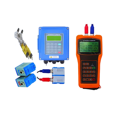
Ultrasonic Flowmeter
| Feature | Description |
|---|---|
| Non-intrusive Measurement | Clamp-on installation, no pipe cutting required |
| No Pressure Loss | No obstruction inside the pipeline |
| High Accuracy & Repeatability | Up to ±0.5% for transit-time type |
| Working Principle | Based on transit-time and Doppler effect |
| Low Maintenance | No moving parts, long service life |
| Application Flexibility | Suitable for large pipe sizes and wide range of liquids |
Key Features
Non-Intrusive Technology
- Clamp-on installation
- No pipe cutting required
Advanced Measurement
- Transit-Time & Doppler principles
- Suitable for clean & dirty fluids
No Pressure Loss
- No obstruction inside pipe
- Maintains system efficiency
High Accuracy
- Up to ±1.5% (transit-time)
- Excellent repeatability
Wide Pipe Size Range
- DN15 to DN6000+
- Ideal for large pipelines
Bi-Directional Measurement
- Measures forward & reverse flow
- Suitable for complex systems
Fluid Compatibility
- Water, oil, chemicals
- Slurry & dirty liquids supported
Easy Installation
- No shutdown required
- Portable models available
Low Maintenance
- No moving parts
- Long service life
Digital Output Options
- 4–20 mA, Pulse, Frequency
- Modbus, HART, RS485
Data Logging & Diagnostics
- Built-in memory
- Self-diagnostic features
Wide Operating Range
- Works in harsh conditions
- Depends on sensor type
Energy Efficient
- Low power consumption
- Battery operation possible
Working Principle
Sensor Arrangement
Two ultrasonic transducers are mounted on the pipe:
In clamp-on type → outside the pipe
In inline type → inside the pipe
Transducers act as both transmitter and receiver
2. Signal Transmission
Ultrasonic pulses are transmitted through the fluid
Signals travel:
o Downstream (with flow)
o Upstream (against flow)
3. Transit-Time Measurement (Clean Fluids)
Time taken for signals is measured in both directions
Due to flow:
Downstream signal → faster
Upstream signal → slower
The time difference (Δt) is calculated
Flow velocity ∝ Time difference
4. Doppler Measurement (Dirty Fluids)
Based on the Doppler Effect
Ultrasonic waves reflect from particles/bubbles in fluid
Frequency shift between transmitted and received signal is measured
Flow velocity ∝ Frequency shift
5. Signal Processing
Electronic unit converts:
Time difference / frequency shift → flow velocity
Using pipe diameter:
Velocity → Volumetric flow rate (m³/h, LPM, )
6. Output Generation
Output signals:
o 4–20 mA
Pulse / Frequency
Modbus / HART
Display shows:
Flow rate
Totalizer
7. Important Working Conditions
Pipe must be completely filled
Proper sensor alignment required
Avoid:
Air bubbles (Transit-Time)
No particles (for Doppler → particles required)
Industrial Applications
Water & Wastewater
- Raw, treated & sewage water measurement
- Used in treatment plants & distribution
Power Plants
- Cooling water flow monitoring
- Boiler feed water systems
- Supports energy management
Oil & Gas Industry
- Crude & refined product measurement
- Pipeline monitoring
- Clamp-on for temporary measurement
Chemical Industry
- Chemicals & solvent measurement
- Suitable for corrosive fluids
HVAC & Building Services
- Chilled & hot water measurement
- Used in central AC systems
Water Distribution
- Leak detection in pipelines
- Non-invasive flow monitoring
Food & Beverage
- Milk, juice & liquid products
- Hygienic non-contact measurement
Pharmaceutical Industry
- Clean & sterile liquid systems
- Accurate process control
General Industrial Use
- Process automation systems
- PLC / SCADA integration
Technical Specifications
| Parameter | Specification |
|---|---|
| Measurement Principle | Ultrasonic Transit-Time / Doppler |
| Flow Range | 0.1 to 10 m/s |
| Accuracy | ±1.5% of reading |
| Repeatability | ±0.2% |
| Pipe Size Range | DN15 to DN6000 |
| Fluid Type | Clean liquids / Slurries (depending on model) |
| Temperature Range | -40°C to 150°C |
| Pressure Range | Up to 100 bar |
| Power Supply | 24V DC / 230V AC |
| Output Signals | 4-20 mA, Pulse, Modbus, HART |
| Protection Class | IP65 / IP68 |
| Installation Type | Clamp-on / Inline |
| Display | LCD with backlight |
| Communication | RS485 / Ethernet (optional) |
Type of Transducer
| Flow Transducer | Model | Measuring Range | Temperature |
|---|---|---|---|
| Clamp On | TS-2 (Small) | DN25–100 | -30°C to 90°C |
| TM-1 (Medium) | DN50–700 | ||
| TL-1 (Large) | DN300–6000 | ||
| High Temp Clamp On | TS-2-HT (Small) | DN25–100 | -30°C to 160°C |
| TM-1-HT (Medium) | DN50–700 | ||
| TL-1-HT (Large) | DN300–6000 | ||
| Insertion | TC-1 (Standard) | DN50–6000 | -30°C to 160°C |
| TC-2 (Extended) | DN50–6000 | ||
| TP-1 (Parallel) | DN200–6000 | ||
| Inline | Standard | DN15–1000 | -30°C to 160°C |
External Clip Probe
| Technical Parameters | Standard Small Sensor | Standard Medium Sensor | Standard Large Sensor |
|---|---|---|---|
| Applicable Pipe Diameter | DN15 – DN100 mm | DN50 – DN700 mm | DN300 – DN3000 mm |
| Material | Polyurethane Alloy | ||
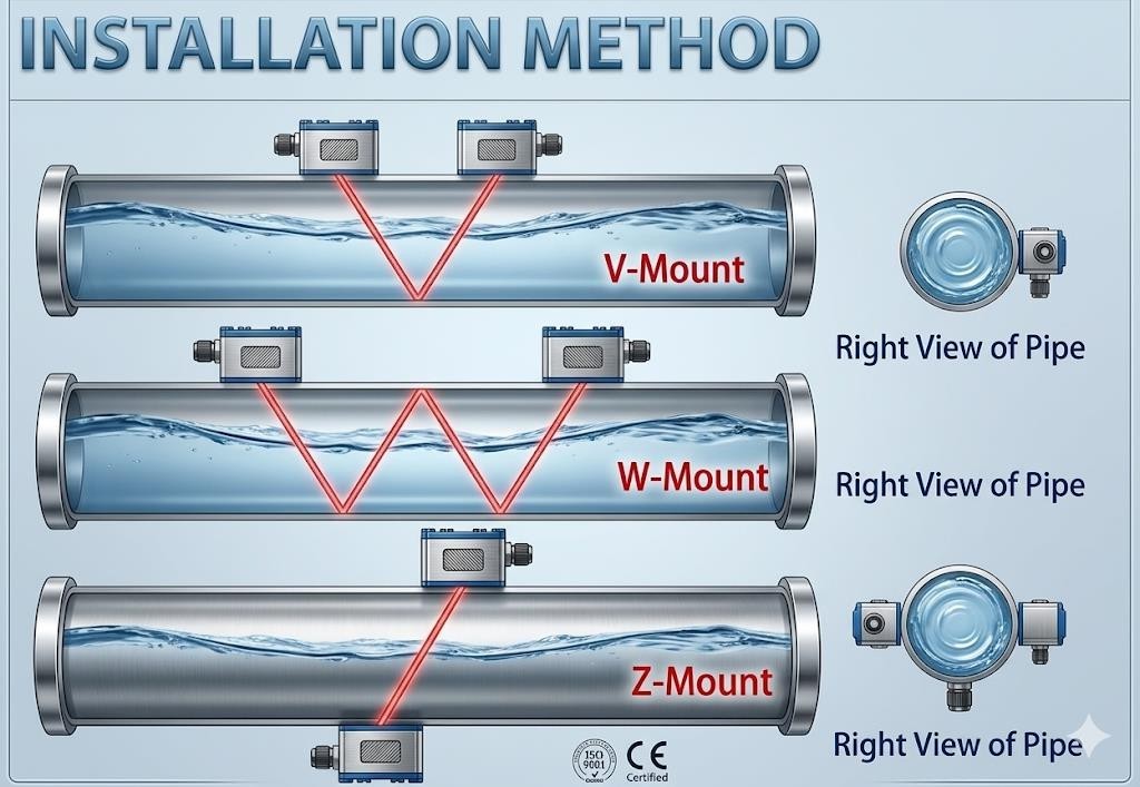
| Working Frequency | 1 MHz | ||
| Installation Method | V (N, W) | V, Z | Z |
| Calibration | Machine Pairing Calibration | ||
| Magnetic | Available | ||
| Operating Temperature | 0 – 80°C | ||
| Protection Level | IP68 (Water-immersible up to 3 meters) | ||
| Medium | Water, sea water, sewage, alcohol, some oils, etc. Suitable for single, uniform and stable liquids that conduct ultrasonic waves. | ||
| Applicable Pipe Material | Carbon steel, cast iron, copper, PVC, aluminum, fiberglass and lined pipes. | ||
| Signal Cable | SV75-2 shielded cable extendable up to 300 meters. Use metal sleeve for anti-interference. Avoid parallel wiring with high-voltage cables and interference sources like inverters. | ||
Model Selection Table
| Parameter | Options |
|---|---|
| Meter Power Supply |
1. 230V AC 2. 24V DC |
| Operating Temperature |
1. Up to 80°C 2. Up to 160°C 3. Please specify |
| Sensor Type |
1. Clamp On 2. Insertion |
| Sensor Size |
1. Small 2. Middle 3. Large |
| Cable Length |
1. Up to 5 meter 2. Above 5 meter |
| Output |
1. 4 to 20 mA 2. Relay 3. Others |
| Communication |
1. RS485 Modbus RTU 2. HART |
| Ingress Protection |
1. IP65 2. IP67 |
| Enclosure Type |
1. Flame Proof 2. Non-Flame Proof |
| Test Certificate |
1. Factory Certificate 2. NABL Traceability |