Vortex Flow Meter
- Home
- Vortex Flow Meter

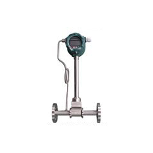
Vortex Flow Meter
| PARAMETER | TYPICAL VALUE |
|---|---|
| Accuracy | ±1.0% (Liquid), ±1.5% (Gas/Steam) |
| Repeatability | ±0.2% |
| Turndown Ratio | 10:1 to 20:1 |
| Response Time | ≤ 1 sec |
| Process Temperature | -40°C to +350°C |
| Output Signal | 4–20 mA, Pulse, Frequency |
| Communication | HART / Modbus (RS485) |
Key Features
No Moving Parts
Ensures minimal wear and tear, resulting in low maintenance and long service life.
High Accuracy & Stability
Provides reliable measurement with excellent repeatability and long-term stability.
Wide Measurement Range
Supports a high turndown ratio (up to 20:1) for various flow conditions.
Multi-Fluid Capability
Suitable for liquids, gases, and steam, making it highly versatile.
Unaffected by Fluid Properties
Performance is largely independent of density, pressure, and temperature variations.
High Temperature & Pressure Resistance
Operates efficiently in extreme industrial environments.
Digital Output & Communication
Supports 4–20 mA, Pulse, HART, and Modbus for easy system integration.
Robust Construction
Made with stainless steel body (SS304/SS316) for durability and corrosion resistance.
Low Pressure Drop
Optimized design ensures minimal energy loss in the pipeline.
Easy Installation & Commissioning
Available in flanged, wafer, and insertion types.
Optional Compensation
Supports temperature and pressure compensation for accurate mass flow measurement.
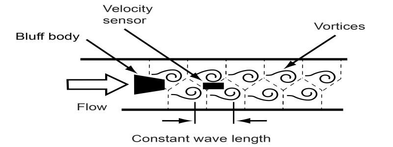
Working Principle
The vortex flow meter works on the Von Kármán vortex street, where a bluff body placed in the flow path generates vortices. The frequency of vortex shedding (f) is directly proportional to the fluid velocity (V):
- f = St × V / d
Where: - f = vortex frequency
- St = Strouhal number (constant)
- V = fluid velocity
- d = width of bluff body
Industrial Applications
Vortex flow meters are widely used in industries where reliable flow measurement of steam, gas, and clean liquids is required.
1. Power Plants
• Steam flow measurement in boilers and turbines
• Feed water and condensate monitoring
• Energy efficiency and heat balance calculations
• Feed water and condensate monitoring
• Energy efficiency and heat balance calculations
2. Oil & Gas Industry
• Measurement of natural gas and compressed air
• Steam injection systems
• Refinery process flow monitoring
• Steam injection systems
• Refinery process flow monitoring
3. Chemical & Petrochemical Industry
• Flow measurement of process gases and liquids
• Utility lines (steam, nitrogen, air)
• Reactor feed and output monitoring
• Utility lines (steam, nitrogen, air)
• Reactor feed and output monitoring
4. Food & Beverage Industry
• Steam flow in sterilization and cooking processes
• Clean liquid measurement (water, beverages)
• Utility monitoring for energy optimization
• Clean liquid measurement (water, beverages)
• Utility monitoring for energy optimization
5. Pharmaceutical Industry
• Steam used in sterilization (SIP/CIP systems)
• Process gas monitoring
• Clean and hygienic flow applications
• Process gas monitoring
• Clean and hygienic flow applications
6. Water & Wastewater Treatment
• Flow measurement of treated water and chemicals
• Aeration systems (air flow monitoring)
• Pumping and distribution systems
• Aeration systems (air flow monitoring)
• Pumping and distribution systems
7. HVAC & Building Services
• Chilled water and hot water flow measurement
• Steam and air flow in heating systems
• Energy management systems (EMS)
• Steam and air flow in heating systems
• Energy management systems (EMS)
8. Pulp & Paper Industry
• Steam flow for drying processes
• Chemical flow monitoring
• Utility management
• Chemical flow monitoring
• Utility management
9. Textile Industry
• Steam usage in dyeing and drying processes
• Compressed air monitoring
• Compressed air monitoring
10. General Industrial Utilities
• Compressed air systems
• Boiler efficiency monitoring
• Energy consumption tracking
• Boiler efficiency monitoring
• Energy consumption tracking
Technical Specifications
| PARAMETER | DETAILS |
|---|---|
| Measured Medium | Liquid, Gas, Steam |
| Medium Temp. | (-)40 ~ +250℃; (-)40 ~ +350℃ (High Temperature Type) |
| Pressure |
Flange: DIN PN10/PN16/PN25/PN40, ANSI 150#/300% Wafer: 4.0 MPa Thread: 1.6 MPa Tri-clamp: 1.6 MPa Insertion: 1.6 MPa |
| Accuracy | ±1.0% (Flange/Wafer/Thread/Tri-clamp) ±1.5% (Insertion Type) |
| Flow Range |
Liquid: 0.4–7.0 m/s Gas: 4.0–60.0 m/s Steam: 5.0–70.0 m/s |
| Specifications |
DN15–DN300 (Flange/Wafer Type) DN80–DN2000 (Insertion Type) DN15–DN100 (Thread/Sanitary Type) |
| Body Material | SS304 (Standard), SS316 (Optional) |
| Reynolds Number | 2 × 10⁴ ~ 7 × 10⁶ |
| Resistance Coefficient | Cd ≤ 2.6 |
| Vibration Acceleration Allowed | ≤ 0.2g |
| Protection Grade | IIG Exia IICT5 Ga |
| Ambient Temperature | (-)40℃ ~ 65℃ (Non Ex-proof) 20℃ ~ 55℃ (Ex-proof) |
| Relative Humidity | ≤ 85% |
| Pressure (Atmospheric) | 86–106 kPa |
| Power Supply | DC 12–30V or 3.6V Lithium Battery |
| Signal Output | 4–20mA, Pulse 2-wire (HART), 4-wire (RS485) |
| Communication | RS485 Modbus or HART |
Flow Range
Selection Of Caliber Of Vortex Flowmeter
Vortex flow sensor operating flow range table
| Caliber (mm) | Liquid | Gas | ||||
|---|---|---|---|---|---|---|
| Range (m³/h) | Output Frequency (Hz) | Small Signal | Measurement Range (m³/h) | Output Frequency (Hz) | Small Signal | |
| 15 | 0.4~4 | 40~400 | 15 | 3.0~12 | 280~1200 | 100 |
| 20 | 0.8~8 | 33~330 | 10 | 6~30 | 230~1100 | 80 |
| 25 | 1.2~12 | 25~250 | 8 | 9~55 | 200~1200 | 70 |
| 32 | 2.0~20 | 20~200 | 6 | 12~120 | 120~1200 | 60 |
| 40 | 3.0~30 | 15~150 | 6 | 20~200 | 100~1000 | 50 |
| 50 | 5.0~50 | 13~130 | 5 | 30~300 | 80~800 | 40 |
| 65 | 8.0~80 | 9.7~97 | 4 | 50~500 | 60~600 | 30 |
| 80 | 12~120 | 7.7~77 | 3 | 80~800 | 50~500 | 25 |
| 100 | 20~200 | 6.7~67 | 2 | 120~1200 | 40~400 | 20 |
| 125 | 30~300 | 5.0~50 | 2 | 200~2000 | 35~350 | 20 |
| 150 | 40~400 | 3.8~38 | 1 | 300~3000 | 30~300 | 15 |
| 200 | 75~750 | 3.0~30 | 1 | 500~5000 | 20~200 | 10 |
| 250 | 110~1100 | 2.3~23 | 1 | 800~8000 | 16~160 | 5 |
| 300 | 160~1600 | 2.0~20 | 1 | 1100~11000 | 13~130 | 5 |
| (300) | 160~1500 | 5.5~87 | 2 | 1560~15600 | 85~880 | 45 |
| (400) | 180~3000 | 5.6~87 | 2 | 2700~27000 | 85~880 | 45 |
| (500) | 300~4500 | 5.6~88 | 2 | 4300~43000 | 85~880 | 45 |
| (600) | 450~6500 | 5.7~89 | 2 | 6100~61000 | 85~880 | 45 |
| (800) | 750~10000 | 5.7~88 | 2 | 11000~110000 | 85~880 | 45 |
| (1000) | 1200~17000 | 5.8~88 | 2 | 17000~170000 | 85~880 | 45 |
Model Selection Table
The Selection Table Of S S Flow Vortex Flowmeter.
| Instrument Type | S S Flow Vortex Flowmeter | |||||||
|---|---|---|---|---|---|---|---|---|
| Nominal Diameter (mm) | 015 | DN15 | 125 | DN125 | 601 | DN600 | 202 | DN2000 |
| 020 | DN20 | 151 | DN150 | 701 | DN700 | |||
| 025 | DN25 | 201 | DN200 | 801 | DN800 | |||
| 032 | DN32 | 251 | DN250 | 901 | DN900 | |||
| 040 | DN40 | 301 | DN300 | 102 | DN1000 | |||
| 050 | DN50 | 351 | DN350 | 122 | DN1200 | |||
| 065 | DN65 | 401 | DN400 | 142 | DN1400 | |||
| 080 | DN80 | 451 | DN450 | 162 | DN1600 | |||
| 101 | DN100 | 501 | DN500 | 182 | DN1800 | |||
| Structure Type | F | Split Type | Y | Integral Type | ||||
| Connection Mode | 1 | Flange connection | ||||||
| 2 | Clamping flange connection | |||||||
| 3 | Insert type | |||||||
| 4 | Thread connection | |||||||
| 5 | Clamp connection | |||||||
| Measurable Medium | L | Liquids | ||||||
| G | Gases | |||||||
| S | Saturated steam | |||||||
| O | Superheated steam | |||||||
| Medium Rating Pressure (MPa) | 16 | Example: 1.6MPa represented as 16 | ||||||
| Medium Maximum Temperature | L | 150°C | ||||||
| M | 250°C | |||||||
| H | 350°C | |||||||
| T | 400°C | |||||||
| Power Supply | 1 | 12~28VDC | ||||||
| 2 | 3.6V Lithium Battery (Live LCD display) | |||||||
| 3 | 85~265VAC (Remote display) | |||||||
| Output Signal | F | No display of pulse output | ||||||
| D | Current output with display | |||||||
| H | RS232/RS485/HART | |||||||
| Function Type | P | With pressure compensation | ||||||
| T | With temperature compensation | |||||||
| PT | With pressure & temperature compensation | |||||||
| Explosion-proof | A | No explosion proof | ||||||
| B | Explosion-proof | |||||||
| G | Flameproof | |||||||
More Products Display
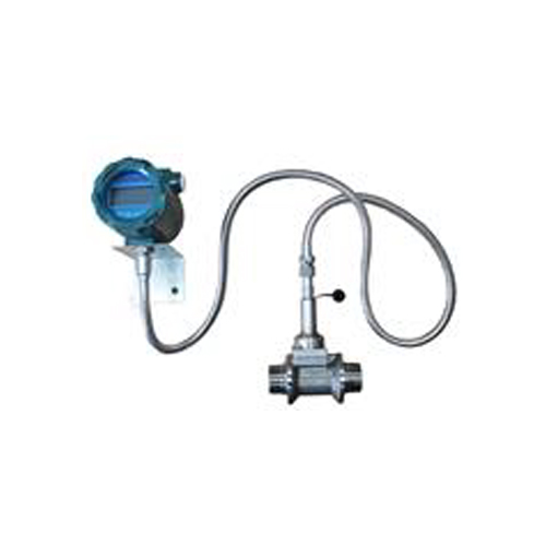
Catonized thread connection vortex flowmeter
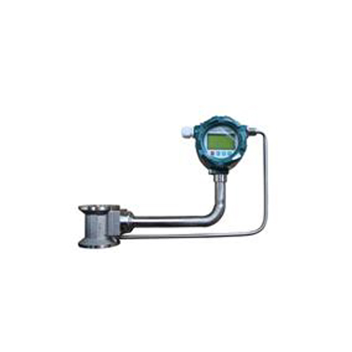
Customized vortex flowmeter