PD flow meter
- Home
- PD flow meter

PD flow meter
| Parameter | Specification |
|---|---|
| Measurement Type | Volumetric Flow |
| Fluid Type | Liquids (clean / viscous / lubricating) |
| Line Size | Up to 300 mm |
| Accuracy | ±0.5% of reading |
| Repeatability | ±0.05% to ±0.2% |
| Temperature Range | -40°C to +150°C (typical) |
Key Features
High Accuracy Measurement
- Accuracy up to ±0.5% of reading
- Ideal for precise flow monitoring
Direct Volumetric Measurement
- Measures actual fluid volume
- No pressure/temperature compensation needed
Excellent Repeatability
- Repeatability up to ±0.05%
- Perfect for batching and dosing applications
Wide Turndown Ratio
- Up to 20:1 turndown ratio
- Handles low to high flow efficiently
High Viscosity Compatibility
- Suitable for oil, fuel, syrup, chemicals
- Performs well with thick fluids
Low Flow Capability
- Accurate at very low flow rates
- Better than many conventional meters
No Straight Pipe Requirement
- Not affected by flow disturbances
- Flexible installation conditions
Robust Mechanical Design
- Durable industrial construction
- Long operational life
Multiple Output Options
- Pulse, 4–20 mA, digital outputs
- Supports modern control systems
Bidirectional Measurement
- Measures forward and reverse flow
- Model dependent feature
Low Power Requirement
- Mechanical versions need no power
- Energy-efficient operation
Material Flexibility
- Available in SS, cast iron, aluminum
- Compatible with various fluids
Easy System Integration
- Works with PLC & SCADA systems
- Suitable for batching automation
Custody Transfer Reliability
- Ideal for billing applications
- Used in fuel & oil transfer systems
Working Principle
A Positive Displacement (PD) Flow Meter works on the principle of trapping and transferring a fixed volume of fluid repeatedly and counting how many times this process occurs.
Step-by-Step Operation :
Fluid Entry
The liquid enters the meter and flows into a chamber containing moving elements
(gears, rotors, pistons, or oval gears).
2. Fixed Volume Trapping
The meter traps a known and fixed quantity of fluid between these moving parts and the meter body.
3. Mechanical Movement
The trapped fluid causes the internal elements (e.g., gears or rotors) to rotate.
4. Displacement Cycle
Each rotation or cycle moves a precise volume of fluid from inlet to outlet.
5. Counting Mechanism
The number of rotations is counted using:
- Mechanical counter, or
- Electronic sensor (pulse output)
6. Flow Calculation
Flow rate is calculated as:
Flow Rate = Number of cycles × Volume per cycle
Simple Formula
Q=N×VQ = N \times VQ=N×V Where:
- Q = Flow rate
- N = Number of rotations (or cycles)
- V = Volume per cycle
Key Concept
- The meter physically measures volume, unlike other meters that infer flow from velocity or pressure.
- That’s why PD meters are highly accurate and reliable, especially for viscous fluids.
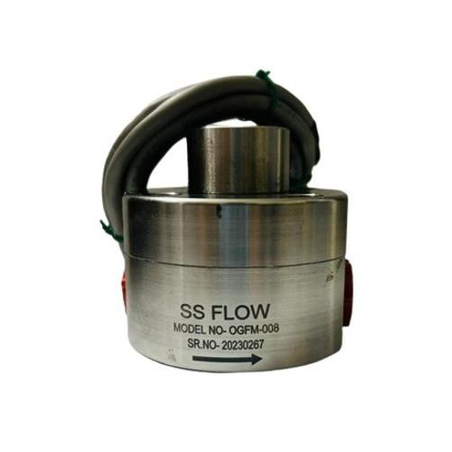
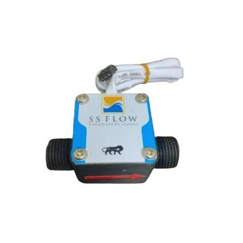
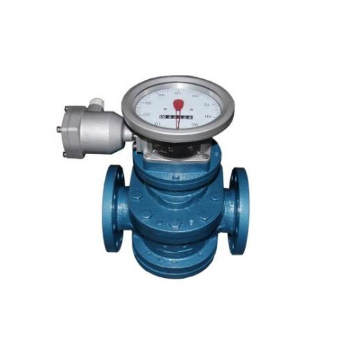
Common Types of PD Mechanisms
- Oval Gear Type
- Gear Flow Meter
- Piston (Reciprocating) Type
- Nutating Disc Type
- Rotary Vane Type
Important Note
- Accuracy depends on tight internal clearances and proper lubrication from the
- Works best with clean and viscous liquids.
Industrial Applications
Oil & Gas Industry
- Crude oil measurement
- Diesel, petrol & fuel oil monitoring
- Custody transfer applications
- Lubricating oil measurement
Chemical & Petrochemical
- Chemical dosing & batching
- Resin, polymer & solvent measurement
- Handles corrosive & viscous fluids
Food & Beverage
- Syrup, honey & chocolate flow
- Dairy products (milk, cream)
- Edible oil measurement
- Beverage batching processes
Pharmaceutical Industry
- Accurate liquid dosing
- Syrup & liquid medicine production
- High-precision batching
Paint & Coating
- Paint, varnish & ink measurement
- High-viscosity fluid handling
- Mixing & blending processes
Power Plants
- Fuel oil consumption measurement
- Burner fuel flow monitoring
- Lubrication system monitoring
Automotive Industry
- Fuel consumption testing
- Engine testing systems
- Lubrication oil measurement
Marine Industry
- Bunker fuel measurement
- Ship fuel consumption monitoring
- Engine fuel systems
Hydraulic & Lubrication
- Oil circulation systems
- Gear & hydraulic oil monitoring
- Precision lubrication control
Custody Transfer Systems
- Fuel loading/unloading terminals
- Tanker loading systems
- Accurate billing applications
Asphalt & Bitumen
- Bitumen flow measurement
- High-temperature viscous fluids
Industrial Process Control
- Pipeline flow measurement
- Batch control systems
- PLC/SCADA integration
Technical Specifications
| Parameter | Options |
|---|---|
| MOC | 1 – SS304 2 – SS316 3 – Aluminium Anodized |
| Protection | 1 – IP65 2 – IP67 |
| Pressure | 1 – Up to 16 Bar 2 – Other |
| Explosion Proof | 1 – Yes 2 – No |
| Connection | 1 – Flange 2 – Thread |
| Output | 1 – 4–20 mA 2 – RS485 3 – 4–20 mA + HART 4 – 4–20 mA + RS485 5 – NPN / PNP |
| Temperature | 1 – 80°C 2 – 120°C 3 – 150°C 4 – Above 150°C |
| Relay | 1 – Switching 2 – Batching 3 – With Additional Output 4 – NA |
| Power | 1 – 24V DC 2 – 230V DC 3 – Other |
| Test Certificate | 1 – Factory Calibration 2 – NABL Lab |
| Display | 1 – Without 2 – Integral 3 – Remote Type |
| Any Other Details | Please specify |