Thermal Mass Flow Meter
- Home
- Thermal Mass Flow Meter
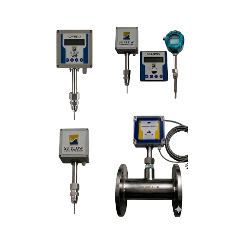
Thermal Mass Flow Meter
| Parameter | Specification |
|---|---|
| Accuracy | 2% Reading |
| Repeatability | 0.5% |
| Turndown Ratio | Up to 100:1 |
| Response Time | ≤ 1 second |
| Operating Pressure | Up to 40 bar (customizable) |
| Operating Temperature | -20°C to +250°C |
| Ambient Temperature | 10°C to +60°C |
Key Features
Direct Mass Flow Measurement
Measures gas mass flow directly without the need for external pressure and temperature compensation.
High Accuracy & Repeatability
Ensures precise and stable measurement even at low flow rates.
Wide Turndown Ratio
Capable of measuring a broad range of flow rates (up to 100:1).
No Moving Parts
Provides long service life with minimal wear and virtually no maintenance.
Low Pressure Drop
Non-intrusive design minimizes impact on system pressure.
Fast Response Time
Quick detection of flow changes for better process control.
Multi-Gas Capability
Suitable for gases such as air, nitrogen, oxygen, biogas, and natural gas.
Robust Construction
Built with high-quality SS 316 / SS 316L materials for harsh industrial environments.
Flexible Installation
Available in insertion and inline types for different pipe sizes.
Multiple Output Options
Supports 4–20 mA, pulse output, and RS485 (Modbus RTU) communication.
User-Friendly Display
Clear LCD/LED display for real-time flow rate and totalized flow.
Energy Monitoring & Leak Detection
Ideal for compressed air systems to improve energy efficiency.
Working Principle
The working principle of a thermal mass flow meter is based on the concept of convective heat transfer. The flow meter consists of a heated element (often referred to as a sensor or probe) and temperature sensors. These sensors are usually located upstream and downstream of the heater. The heater continuously maintains a constant temperature difference (ΔT) relative to the fluid. As the fluid flows past the heated element, it absorbs heat due to convective heat transfer. The temperature sensors measure the temperature difference (ΔT) between the heated element and the fluid. This temperature difference is directly proportional to the rate at which heat is carried away by the fluid, which in turn correlates with the mass flow rate of the fluid. By knowing the heat input (power supplied to the heater) and monitoring the temperature difference (ΔT), the mass flow rate of the fluid can be calculated using specific calibration factors and the physical properties of the fluid (such as thermal conductivity and specific heat).The flow meter processes this data to provide an output signal that directly indicates the mass flow rate of the fluid.
Industrial Applications
Thermal Mass Flow Meters are widely used across industries for accurate measurement and control of gas flow. Their direct mass flow measurement capability, without requiring temperature or pressure compensation, makes them ideal for various industrial processes.
Oil & Gas Industry
- Natural gas flow measurement in pipelines
- Flare gas monitoring and control
- Gas distribution and custody transfer (non-fiscal)
- Fuel gas flow measurement in burners and heaters
Chemical & Petrochemical Plants
- Process gas flow monitoring
- Reactor feed gas control
- Inert gas flow measurement (Nitrogen, Argon)
- Gas blending and batching systems
Power Plants
- Combustion air flow measurement
- Boiler fuel gas monitoring
- Primary and secondary air measurement
- Stack emission monitoring
Steel & Metallurgy Industry
- Blast furnace gas measurement
- Coke oven gas flow monitoring
- Oxygen and nitrogen supply control
- Compressed air distribution
Pharmaceuticals & Biotechnology
- Clean gas flow measurement (O₂, N₂, CO₂)
- Fermentation air control
- Process gas monitoring in sterile environments
- Utility gas measurement
Food & Beverage Industry
- CO₂ flow measurement in carbonation
- Nitrogen flushing and packaging
- Compressed air monitoring
- Utility gas management
Cement Industry
- Kiln combustion air measurement
- Preheater and calciner gas monitoring
- Bag filter and dust collector airflow
- Compressed air system monitoring
Water & Wastewater Treatment
- Aeration air flow measurement
- Digester gas monitoring (biogas)
- Blower air flow control
- Methane gas measurement
Semiconductor & Electronics Industry
- High-purity gas flow measurement
- Process gas control in fabrication
- Cleanroom gas monitoring
- Specialty gas applications
General Industrial Utilities
- Compressed air consumption monitoring
- Leak detection systems
- HVAC air flow measurement
- Energy management systems
Technical Specifications
| Parameters | Details |
|---|---|
| Measuring Medium | Gas (Except Acetylene & Steam) |
| Velocity | 0.1 – 100 Nm/s |
| Accuracy |
±2.5% / ±1.5% Reading (Insertion) ±1% Reading (Flange) |
| Response Time | 1 second |
| Output | 4–20 mA (optoelectronic isolation, max load 500Ω), Pulse, RS485 (Modbus), HART |
| Power Supply |
Compact: 24VDC or 220VAC (Power Consumption ≤18W) Remote Type: 220VAC (Power Consumption ≤19W) |
| Working Pressure |
Insertion Type ≤1.6 MPa Flange Type ≤4.0 MPa Tri-Clamp ≤1.6 MPa Thread ≤4.0 MPa |
| Ambient Temperature | -20℃ ~ 50℃ |
| Medium Temperature | -20℃ ~ 150℃ (Customizable up to 400℃ in remote version) |
| Transmitter Housing | Die-cast Aluminium |
| Cable Entry | M20×1.5 Standard, 1/2" NPT Optional |
| Ingress Protection | IP65 / Explosion Proof |
| Display | 4 Digit LCD – Mass Flow, Volume Flow, Flow Totalizer |
| Flow Units | Nm³/h, Nm³/min, kg/h, kg/min and more |
| Alarm Output | 2 Relays, 3A / 250VAC, 3A / 30VDC |
| Structure Type | Remote or Integral |
| Cable Length (Remote) | Standard 10 meters |
| Pipe Material | Carbon Steel, Stainless Steel, Plastic |
| Insertion Type |
Size: DN32 – DN4000 mm Rod, Valve, Sensor Material: SS304 / SS316L / SS316 |
| Flange Type |
Size: DN10 – DN300 (Can be designed above DN300) Flange Standard: ANSI, DIN Tube Material: SS304 / SS316L / SS316 Sensor Material: SS304 / SS316L / SS316 Flange Material: SS304 / SS316L / SS316 |
| Tri-Clamp Type |
Size: DN10 – DN100 Tube Material: SS304 / SS316 Sensor Material: SS316 |
| Thread Type |
Size: DN10 – DN100 Tube Material: SS304 / SS316L / SS316 Sensor Material: SS304 / SS316L / SS316 |
Flow & Velocity Table
| Size (DN) | Min Velocity (Nm/s) | Max Velocity (Nm/s) | Min Flow (Nm³/h) | Max Flow (Nm³/h) |
|---|---|---|---|---|
| 10 | 0.1 | 100 | 0.028 | 28.27 |
| 15 | 0.1 | 100 | 0.063 | 63.61 |
| 20 | 0.1 | 100 | 0.113 | 113.09 |
| 25 | 0.1 | 100 | 0.176 | 176.71 |
| 32 | 0.1 | 100 | 0.289 | 289.52 |
| 40 | 0.1 | 100 | 0.452 | 452.38 |
| 50 | 0.1 | 100 | 0.706 | 706.85 |
| 65 | 0.1 | 100 | 1.194 | 1194.59 |
| 80 | 0.1 | 100 | 1.809 | 1809.55 |
| 100 | 0.1 | 100 | 2.827 | 2827.43 |
| 125 | 0.1 | 100 | 4.417 | 4417.86 |
| 150 | 0.1 | 100 | 6.361 | 6361.72 |
| 200 | 0.1 | 100 | 11.309 | 11309.73 |
| 250 | 0.1 | 100 | 17.671 | 17671.45 |
| 300 | 0.1 | 100 | 25.446 | 25446.90 |
| 350 | 0.1 | 100 | 34.636 | 34636.05 |
| 400 | 0.1 | 100 | 45.238 | 45238.93 |
| 450 | 0.1 | 100 | 57.255 | 57255.52 |
| 500 | 0.1 | 100 | 70.685 | 70685.83 |
| 600 | 0.1 | 100 | 101.787 | 101787.60 |
| 700 | 0.1 | 100 | 138.544 | 138544.23 |
| 800 | 0.1 | 100 | 180.955 | 180955.73 |
| 900 | 0.1 | 100 | 229.022 | 229022.10 |
| 1000 | 0.1 | 100 | 282.743 | 282743.33 |
Model Selection Table
| Parameter | Options |
|---|---|
| Model | SS FLOW_TMFM_LINE |
| Size | Specify Pipe Size |
| MOC |
1 – SS304 2 – SS316 3 – Other |
| Protection |
1 – IP65 2 – IP67 |
| Pressure |
1 – Up to 16 Bar 2 – Other |
| Explosion Proof |
1 – Yes 2 – No |
| Connection |
1 – Flange 2 – Thread 3 – Clamp 4 – Insertion |
| Output |
1 – 4–20 mA 2 – RS485 3 – 4–20 mA + Pulse 4 – 4–20 mA + HART 5 – 4–20 mA + RS485 6 – 4–20 mA + Pulse + RS485 |
| Temperature |
1 – 80°C 2 – 150°C 3 – 250°C 4 – Above 250°C |
| Relay |
1 – Switching 2 – With Additional Output 3 – NA |
| Power Supply |
1 – 24V DC 2 – 230V DC |
| Test Certificate |
1 – Factory Calibration 2 – NABL Lab |