Turbine Flow Meter
- Home
- Turbine Flow Meter

Turbine Flow Meter
| Sr. | Features |
|---|---|
| 1 | High accuracy (typically ±0.5% of reading) |
| 2 | Excellent repeatability |
| 3 | Fast response to flow changes |
| 4 | Wide flow measurement range |
| 5 | Suitable for clean liquids and gases |
| 6 | Compact and lightweight design |
| 7 | Easy installation and maintenance |
| 8 | Good for high-pressure and high-temperature applications |
Key Features
High Accuracy
- Typically ±0.5% to ±1% of reading
- Suitable for precise flow measurement
Wide Flow Range
- Turndown ratio up to 10:1 or higher
- Handles varying flow rates efficiently
Fast Response Time
- Immediate response to flow changes
- Ideal for dynamic systems
Repeatability
- Excellent repeatability (±0.1%)
- Consistent performance over time
Digital / Pulse Output
- Generates frequency or pulse signals
- Easy integration with PLC & SCADA
Compact Design
- Compact & lightweight construction
- Easy installation in pipelines
Low Pressure Drop
- Minimal obstruction to flow
- Energy-efficient operation
Clean Fluid Application
- Suitable for low-viscosity liquids & gases
- Not ideal for slurry or dirty fluids
Temperature & Pressure Capability
- Operates under high pressure & temperature
- Depends on material selection
Material Options
- Stainless Steel, Carbon Steel etc.
- Compatible with industrial fluids
Bidirectional Measurement
- Optional flow measurement in both directions
Easy Maintenance
- Simple construction
- Serviceable bearings and rotor
Working Principle
A turbine flow meter is used for volumetric total flow and/or flow rate measurement and has a relatively simple working principle. As fluid flows through the turbine meter, it impinges upon turbine blades that are free to rotate about an axis along the center line of the turbine housing. The blades are built from a paramagnetic material. Pick-offs, mounted externally without contact with the fluid, create a magnetic field in the pipe. Thus, when the blades pass through this field, they generate a voltage proportional to the velocity of rotation, which can be used to calculate the flow rate. The signal from the pick-offs can go into an external transmitter and convert to other types of communication. You can also use a pre-amplifier to read these pulses directly from the turbine flow meter without the transmitter.
Industrial Applications
Oil & Gas Industry
- Measurement of crude oil, diesel, petrol, and lubricants
- Used in custody transfer and pipeline monitoring
- Fuel flow measurement in refineries
Chemical Industry
- Accurate flow measurement of chemicals and solvents
- Suitable for low-viscosity clean liquids
- Used in batch processing and dosing systems
Power Plants
- Measurement of fuel oil supply to boilers
- Monitoring of cooling water and auxiliary fluids
- Used in energy management systems
Food & Beverage Industry
- Measurement of milk, edible oil, juices and beverages
- Used in filling, batching and blending processes
- Hygienic versions available (SS construction)
Pharmaceutical Industry
- Precise flow measurement in liquid drug production
- Used in clean and sterile processing systems
- Ensures accurate ingredient dosing
Automotive Industry
- Fuel consumption testing for engines and vehicles
- Used in R&D laboratories and test benches
Fuel Management Systems
- Used in fuel dispensing systems
- Monitoring of diesel generators and storage tanks
Water & Light Liquids
- Measurement of clean water and light hydrocarbons
- Used in industrial water treatment plants
Industrial Process Control
- Integrated with PLC / SCADA systems
- Used for real-time flow monitoring and automation
Technical Specifications
| Parameter | Details |
|---|---|
| Line Size | DN4 to DN200 |
| Ratio of Measuring Range | 1:10 |
| Instrument Material | SS316 / SS304 |
| Environment Temperature | -30℃ to 60℃ |
| Medium Temperature | -100℃ to 100℃ / 120℃ / 150℃ |
| Pressure Level | Up to 16 bar (High Pressure Model Available) |
| Power Supply | 12–24V DC / 230V AC |
| Power Consumption | ≤ 1W |
| Signal Output | Pulse / 4–20mA / RS485 (Modbus-RTU) |
| Protection Level | IP65 (IP67 customizable) |
| Explosion Proof | Ex-Proof model available on request |
| Display | Instantaneous flow and accumulative flow with selectable units |
Flow vs Line Size Table
| Diameter (mm) | Std. Flow Range (m³/hr) | Extended Flow Range (m³/hr) |
|---|---|---|
| 4 | 0.04 – 0.25 | 0.04 – 0.4 |
| 6 | 0.1 – 0.6 | 0.06 – 0.6 |
| 10 | 0.2 – 1.2 | 0.15 – 1.5 |
| 15 | 0.6 – 6 | 0.4 – 8 |
| 20 | 0.8 – 8 | 0.45 – 9 |
| 25 | 1 – 10 | 0.5 – 10 |
| 32 | 1.5 – 15 | 0.8 – 15 |
| 40 | 2 – 20 | 1 – 20 |
| 50 | 4 – 40 | 2 – 40 |
| 65 | 7 – 70 | 4 – 70 |
| 80 | 10 – 100 | 5 – 100 |
| 100 | 20 – 200 | 10 – 200 |
| 125 | 25 – 250 | 13 – 250 |
| 150 | 30 – 300 | 15 – 300 |
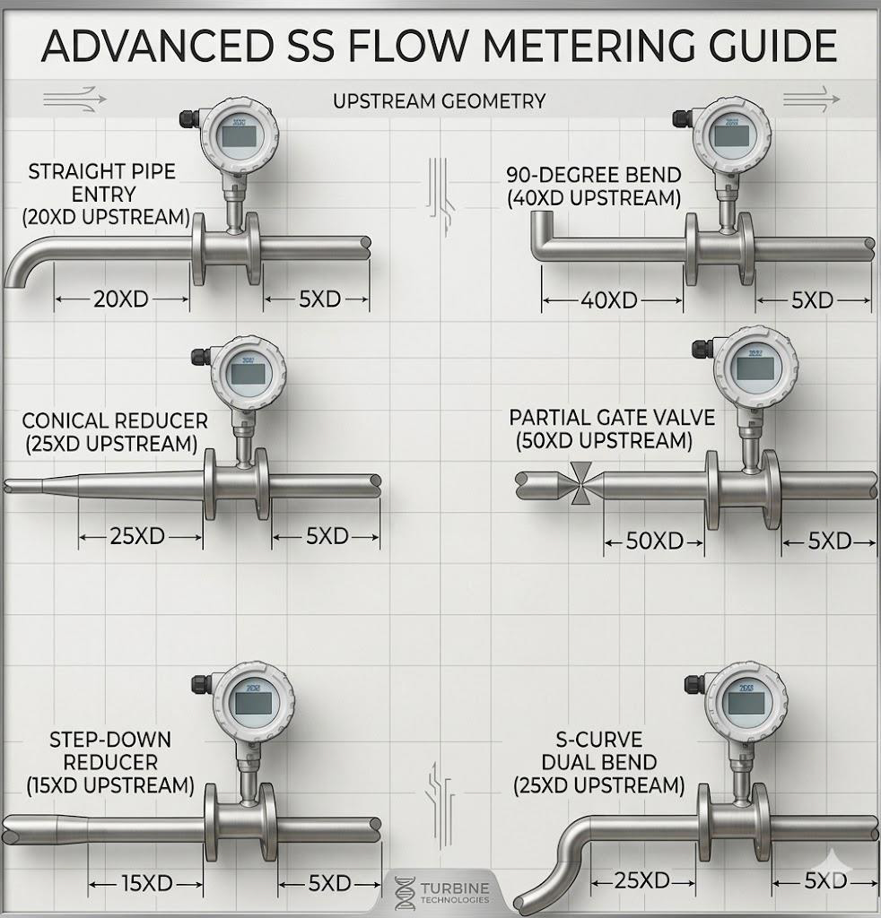
Installation Requirement
1. Straight Pipe Length
- Upstream: Minimum 10–20 D
- Downstream: Minimum 5–10 D
- Avoid near elbows, valves, pumps, reducers
2. Flow Direction
- Follow arrow marking on meter
- Wrong direction may cause errors/damage
3. Fluid Condition
- Clean and particle-free fluid
- Low viscosity recommended
- Use upstream strainer/filter
4. Installation Orientation
- Horizontal preferred
- Vertical (flow upward)
- Pipe must remain full
5. Air / Gas Entrapment
- No air bubbles or vapor
- Use air eliminators if needed
6. Pressure & Temperature
- Operate within limits
- Avoid water hammer
7. Electrical Installation
- Proper grounding required
- Use shielded cables
- Avoid high-voltage interference
8. Vibration & Stress
- Avoid high vibration areas
- Use proper pipe supports
9. Valve Installation
- Install valves downstream
- Avoid upstream valve placement
10. Maintenance Access
- Ensure removal space
- Use bypass line
11. Calibration
- Calibrate before use
- Check zero flow & signal output
- Ensure leak-tight installation
Model Selection Table
| Parameter | Options |
|---|---|
| MOC | 1 – SS304 / 2 – SS316 / 3 – Other |
| Protection | 1 – IP65 / 2 – IP67 |
| Pressure | 1 – Up to 16 Bar / 2 – Other |
| Explosion Proof | 1 – Yes / 2 – No |
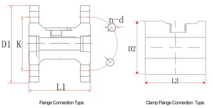
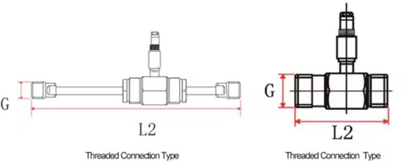
| Connection | 1 – Flange / 2 – Thread / 3 – Clamp / 4 – Insertion |
| Output | 1 – 4 to 20mA / 2 – RS485 / 3 – 4 to 20mA + HART / 4 – 4 to 20mA + RS485 |
| Temperature | 1 – 80°C / 2 – 120°C / 3 – 150°C / 4 – Above 150°C |
| Relay | 1 – Switching / 2 – Batching / 3 – With Additional Output / 4 – NA |
| Power | 1 – 24V DC / 2 – 230V AC / 3 – Other |
| Test Certificate | 1 – Factory Calibration / 2 – NABL Lab |
| Display | 1 – Without / 2 – Integral / 3 – Remote Type |
| Any Other Details | Please Specify |